Harmony PI Filters are in stock. Order direct or through DigiKey.

Case studies

Fifteen measured results, from a 15 fs clock for AI optics and a 59 GHz oscilloscope in a data-center lab to a bracelet that runs on body heat. Each one gives the setup, the instrument and the source document. Click any chart to enlarge it.

NewAI data center and optics

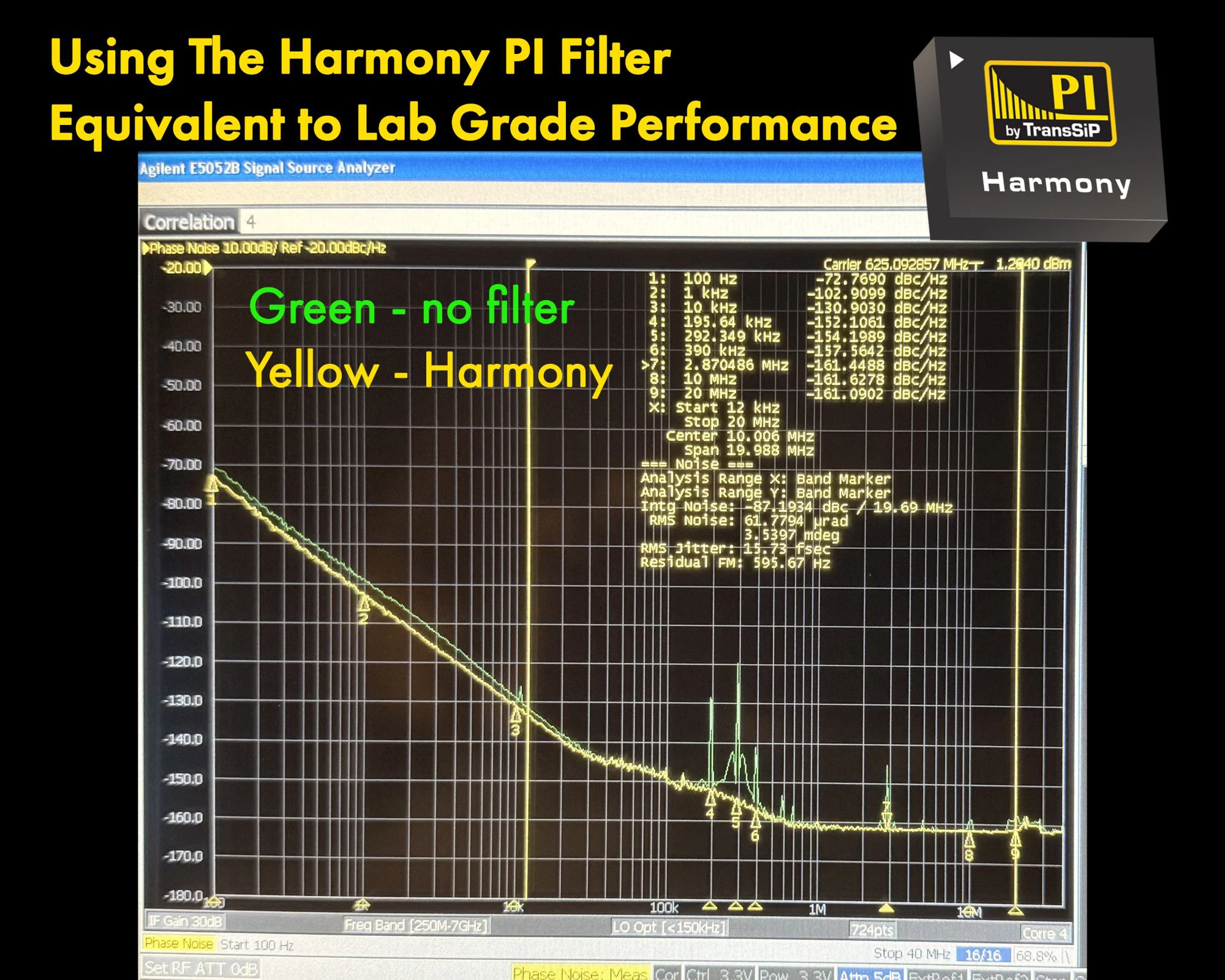
A 625 MHz clock at 15.73 fs, lab-grade from its own supply

15.73 fsRMS jitter at 625 MHz, 12 kHz to 20 MHz

A 625 MHz ultra-low-jitter LVDS differential oscillator for optical modules, AI servers, SerDes and high-speed networking, with Harmony on its 3.3 V supply.

  • With Harmony, RMS jitter measured 15.73 fs from 12 kHz to 20 MHz on the 625.09 MHz carrier. Integrated phase noise is −87.2 dBc.
  • Without a filter, supply spurs stand out of the phase-noise curve from about 10 kHz to 20 MHz, the largest near 200 kHz. With Harmony, every one of them is gone.
  • The floor holds at −161 dBc/Hz from 2.9 MHz to 20 MHz, the performance you would expect from a lab-grade supply.

Setup. Tai-SAW 625 MHz LVDS differential oscillator at 3.3 V, without a filter and with Harmony on its supply. Agilent (Keysight) E5052B signal source analyzer, correlation 4. Tai-SAW Technology is a TransSiP PI solutions partner: small quantities through Tai-SAW, 1,000 pieces or more from TransSiP.

Source: TransSiP 625 MHz demo, Agilent E5052B measurement
Power conversion

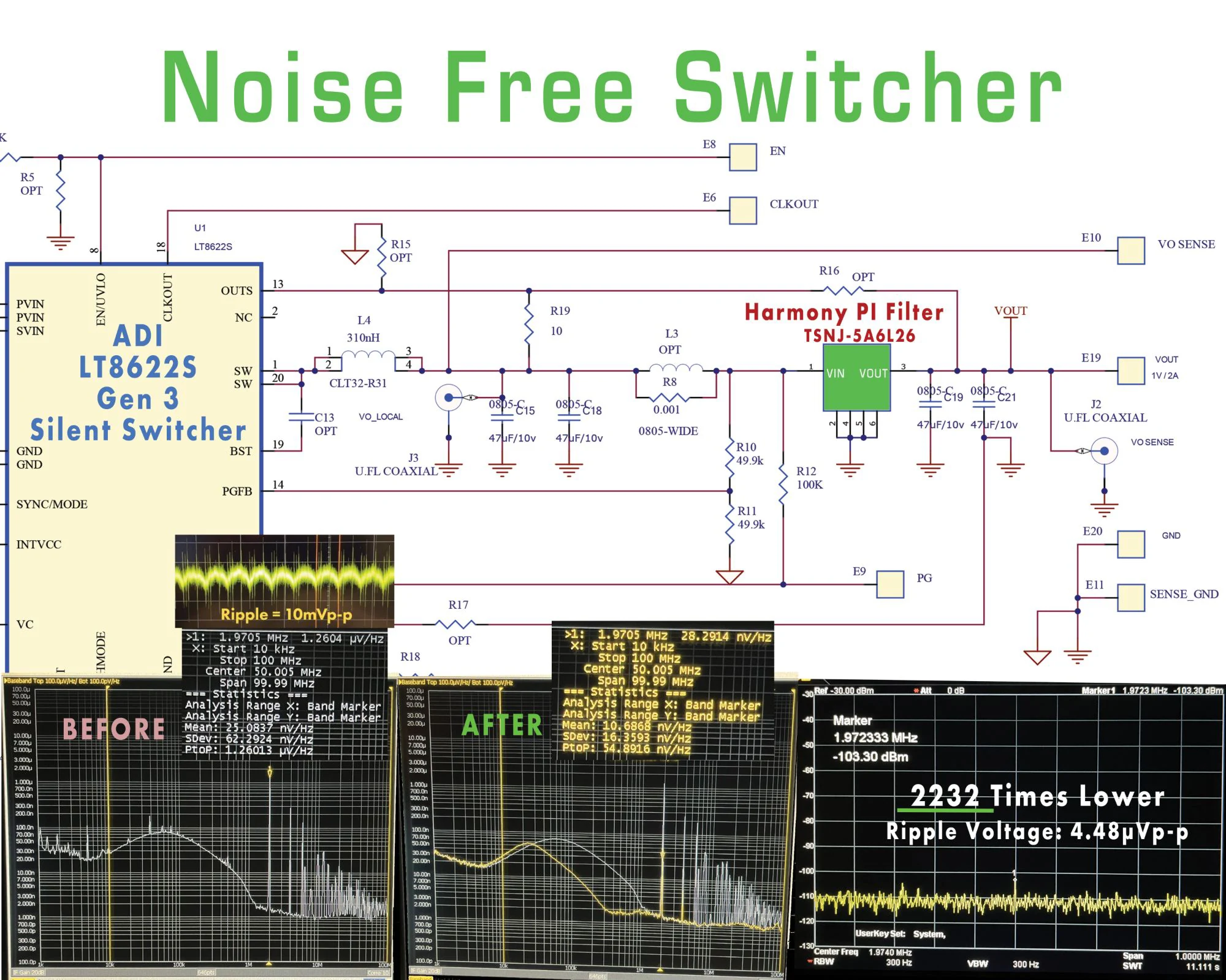
ADI’s LT8622S Silent Switcher, made noise-free

2,232×lower output ripple

Harmony and two 47 µF capacitors at the 1 V, 2 A output of the LT8622S evaluation board.

  • Ripple fell from 10 mVp-p to 4.48 µVp-p. The 1.97 MHz fundamental now reads −103.3 dBm.
  • Mean noise density from 10 kHz to 100 MHz fell from 25.1 to 10.7 nV/√Hz.
  • Switching harmonics and microwave spurs were removed.
  • Harmony revealed the Silent Switcher’s true noise floor: 20 dB lower than the ADI datasheet shows.

Setup. ADI LT8622S Gen 3 Silent Switcher evaluation board, with Harmony Type-B at VOUT. The related video series was made in collaboration with ADI and Keysight.

Source: ADI LT8622S Noise Free Silent Switcher poster (2025)

NewUltra-low-noise LDOs

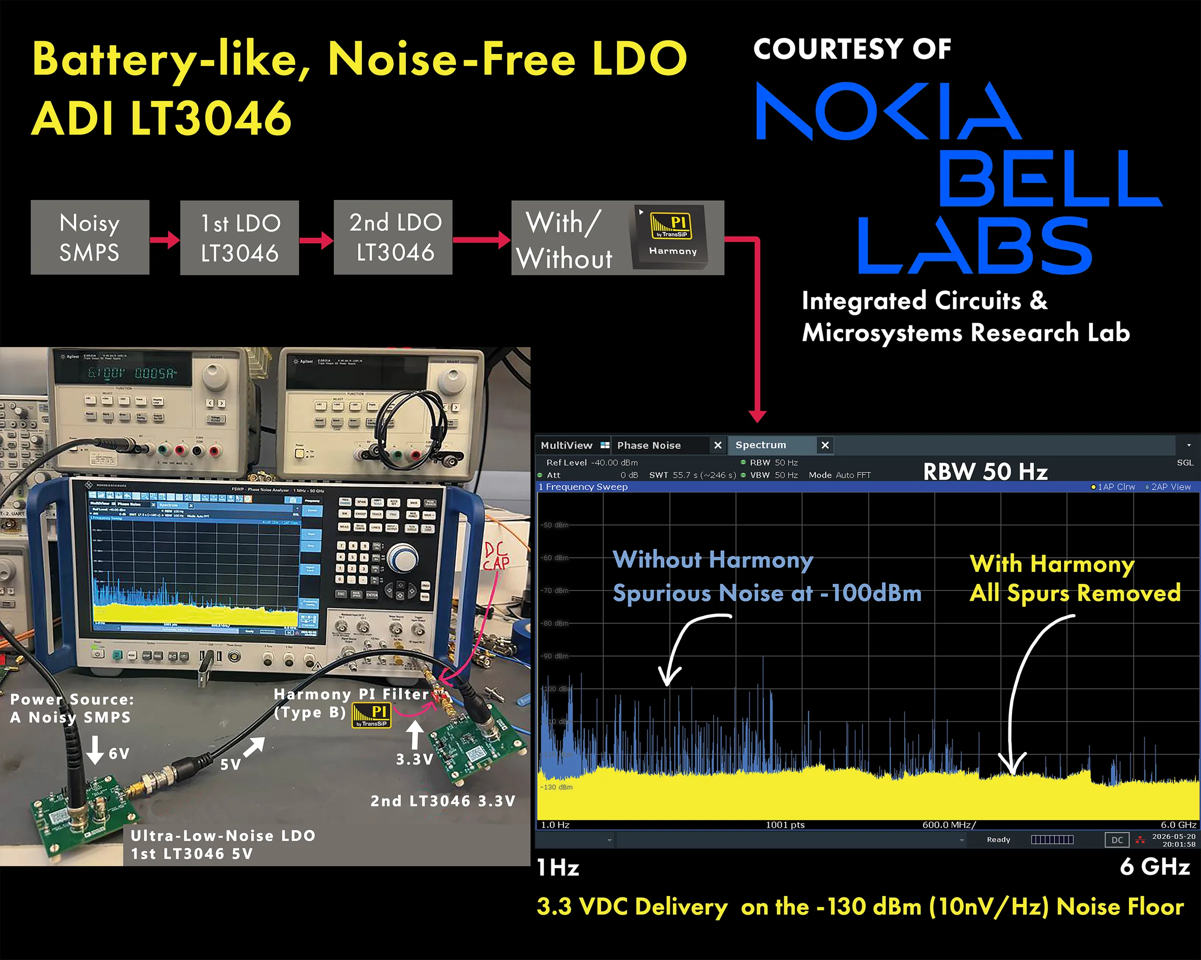
ADI’s LT3046, made battery-like and noise-free

−130 dBmnoise floor at 3.3 V, with every spur removed

The newest result, shared by Nokia Bell Labs: two LT3046 ultra-low-noise LDOs in series, fed from a noisy switcher.

  • A noisy SMPS at 6 V feeds a first LT3046 at 5 V, then a second LT3046 at 3.3 V.
  • Without Harmony, spurious noise still reached about −100 dBm, even after two of ADI’s ultra-low-noise LDOs.
  • With Harmony Type-B after the second LDO, every spur was removed. The 3.3 V rail sits on the −130 dBm (10 nV/√Hz) noise floor from 1 Hz to 6 GHz.

Setup. Noisy SMPS, then LT3046 at 5 V, then LT3046 at 3.3 V, with and without a Harmony Type-B evaluation board. Swept from 1 Hz to 6 GHz at 50 Hz resolution bandwidth.

Source: Courtesy of Nokia Bell Labs, Integrated Circuits & Microsystems Research Lab

AI data center and optics

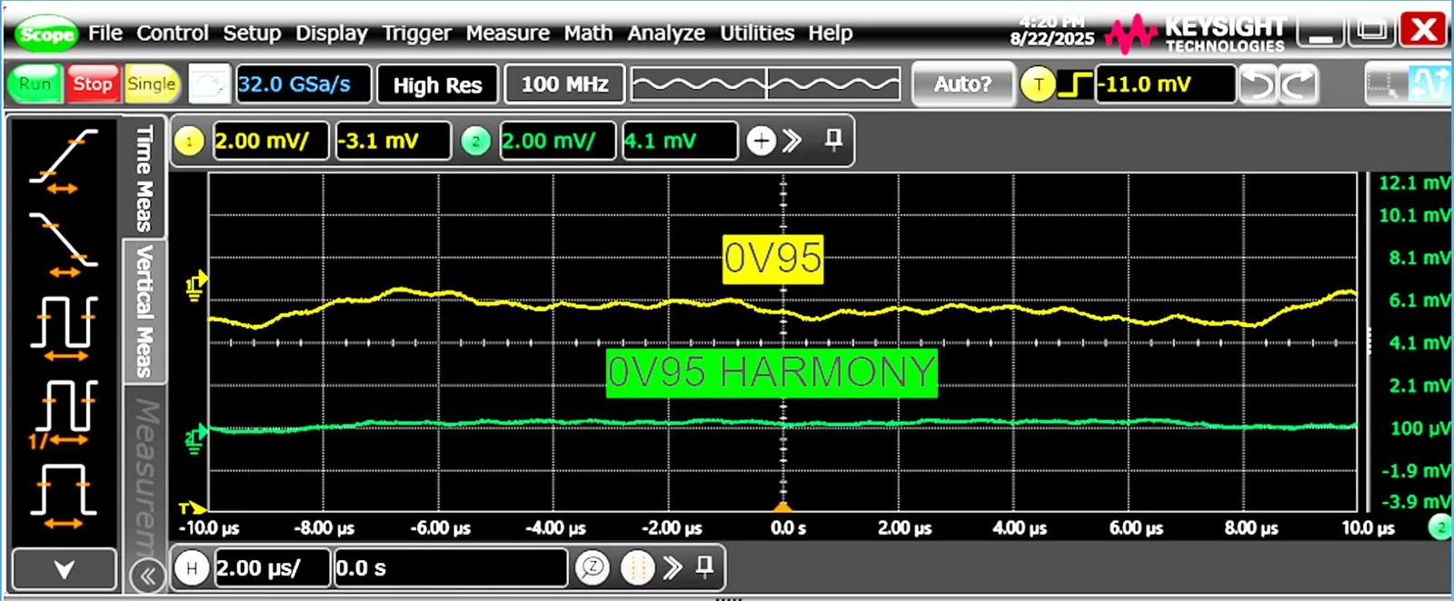
A flat switching rail inside a high-speed laser source

0.95 V, 4 Awith no visible ripple

Validated by a market leader in a high-speed laser source, on a 59 GHz real-time oscilloscope.

  • Without Harmony, the loaded 0.95 V switching rail shows millivolts of ripple at 2 mV/div.
  • With Harmony, the trace is flat on the 100 µV scale.
  • It is the first flat, ripple-free SMPS bias we have seen at this bandwidth.

Setup. Keysight UXR0594A real-time oscilloscope: 59 GHz, 256 GSa/s, 10-bit. SMPS at 0.95 V and 4 A load, August 2025.

Source: Noise Free Innovations 26V2, p. 8

Clocks and timing

Clock phase noise with 200 mVp-p on the supply

18–30 dBlower phase noise, 20 kHz to 2 MHz

A differential crystal oscillator for data-center links, tested with deliberate supply noise.

  • At 20 kHz offset, phase noise improved from −123.8 to −153.3 dBc/Hz.
  • At 1 MHz offset, it improved from −144.1 to −162.4 dBc/Hz.
  • The improvement narrows to 1.4 dB at 10 MHz, where the oscillator’s own floor dominates.

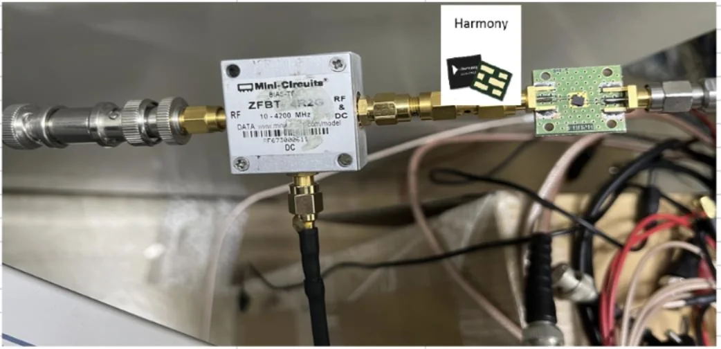
Setup. Power-supply phase-noise (PSPN) test: 200 mVp-p signal injected through a bias tee, XO alone versus XO with Harmony.

Source: Noise Free Innovations 26V2, p. 9

Wireless and 5G

Lab-grade 5G clock jitter from a noisy 3.3 V rail

233 → 20 fsRMS jitter, 12 kHz to 20 MHz

A 122.88 MHz VCXO powered from a noisy 3.3 V PDN, the way it runs in real 5G equipment.

  • On the noisy PDN alone, RMS jitter measured 233 fs.
  • With Harmony Type-B on the same rail, it measured 20 fs. The lab reference with a Keysight E5052B clean bias is 18 fs.
  • An earlier, unoptimized demo board measured 32 fs.

Setup. Keysight E5052B signal source analyzer. Harmony Type-B EVB connected by SMA between the supply and the VCXO VCC.

Source: TransSiP Noise Free ULPN 122.88 MHz VCXO 25V1; Quick Start Guide 25V3, §9

Ultra-low-noise LDOs

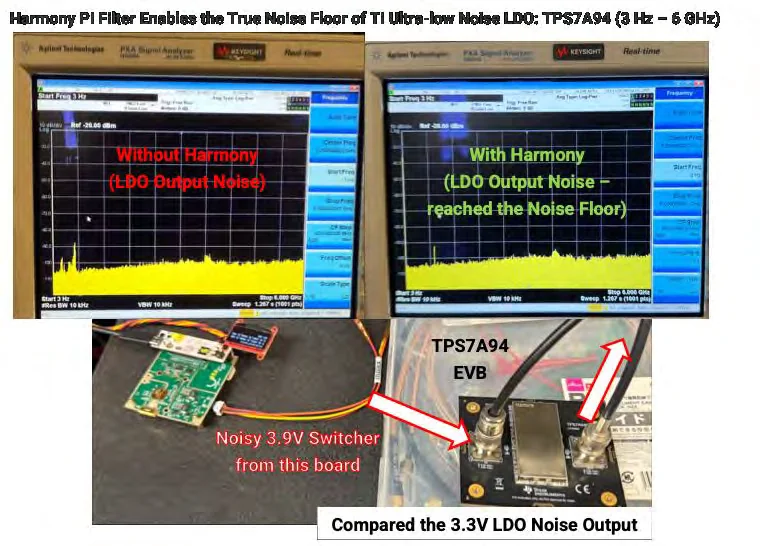
TI’s lowest-noise LDO, taken to the analyzer floor

3 Hz–6 GHzat the spectrum analyzer’s noise floor

Measured with Nokia Bell Labs: a TPS7A94 fed from a noisy 3.9 V DC-DC.

  • With the TPS7A94 alone, noise above 100 kHz was not suppressed, despite the filters under the EVB’s metal lid.
  • With Harmony Type-B at the LDO’s 3.3 V output, the noise reached the floor of the Keysight PXA analyzer.
  • Harmony Type-B on the noisy 3.9 V DC-DC alone, with no LDO, gave the same result.

Setup. TI TPS7A94 EVB converting 3.9 V to 3.3 V, swept from 3 Hz to 6 GHz on a Keysight PXA signal analyzer.

Source: Harmony Quick Start Guide 25V3, §6

Defense radio

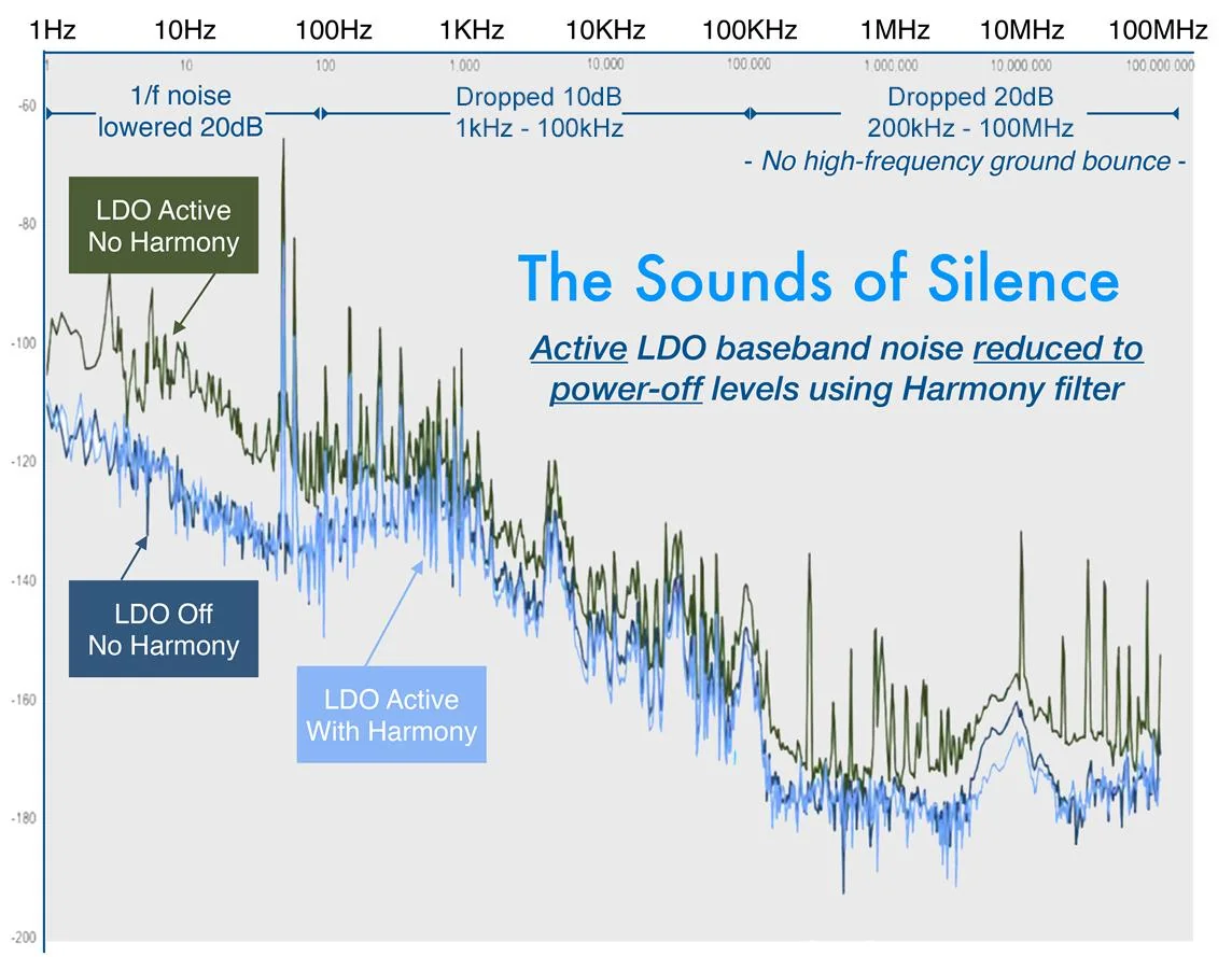
An ADM7150’s baseband noise, reduced to power-off levels

20 dBless 1/f noise

An operational test by a defense entity on an ultra-low-noise, high-PSRR LDO inside a radio system.

  • 1/f noise fell 20 dB from 1 Hz to 100 Hz.
  • Noise fell 10 dB from 1 kHz to 100 kHz, and 20 dB from 200 kHz to 100 MHz.
  • No high-frequency ground bounce remained. The active LDO measured like an LDO switched off.

Setup. ADM7150 in a radio system under real-world conditions, with Harmony and a bulk capacitor at its output. Reproduced by permission.

Source: Noise Free Innovations 26V2, p. 13; EVB Read Me, p. 14

PDN noise

Three parts against a 15-part 6 GHz filter

93%less PCB area, and a noise-free rail

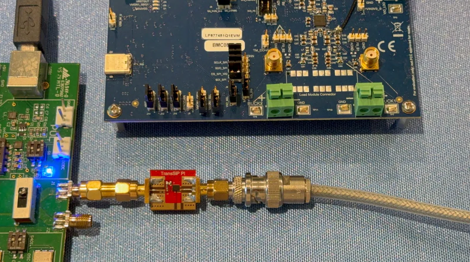
A high-noise 3.3 V rail from a Picotest VRTS3 board, filtered two ways.

  • TI’s 6 GHz broadband filter on the LP877451Q1EVM uses 15 passives. It left the rail “still noisy, just enough to pass EMI”.
  • Harmony Type-B uses three parts. It brought the rail to −99.97 dBm, the analyzer’s own floor, from 9 kHz to 3.2 GHz.
  • The filter area shrank from 112 mm² to 7.7 mm².

Setup. Picotest VRTS3: a TI LMR10515 buck converting USB 5 V to 3.3 V, with its 125 MHz and 10 MHz clocks on. Rigol DSA832 spectrum analyzer.

Source: Why Classic Target Impedance Approach Not Effective 25V3; Noise Free Innovations 26V2, p. 5

PDN impedance

A PDN that is flat in micro-ohms

7,400×lower peak impedance

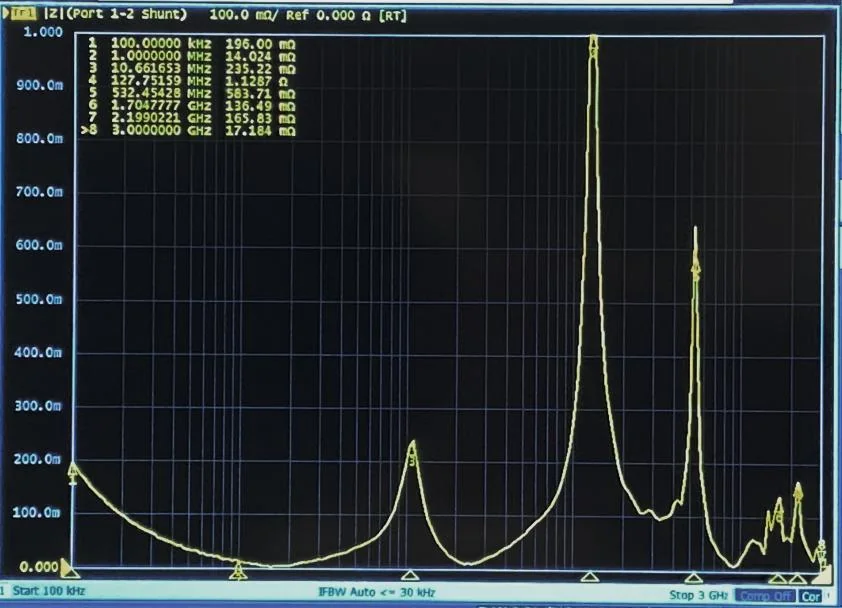
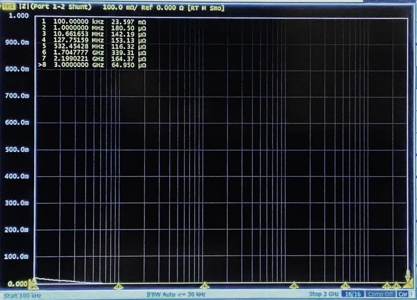
Shunt impedance of a working PDN from 100 kHz to 3 GHz, before and after Harmony.

  • Before: resonances of 1.13 Ω at 127.8 MHz and 584 mΩ at 532 MHz.
  • After: 116 to 339 µΩ from 1 MHz to 3 GHz.
  • With no resonances, there is no phase change across the band.

Setup. Vector network analyzer, 2-port shunt-through impedance, 100 kHz to 3 GHz.

Source: Noise Free Innovations 26V2, p. 11

RF front ends

Two Skyworks front-end modules, 16 decoupling parts to 3

16 → 3decoupling components

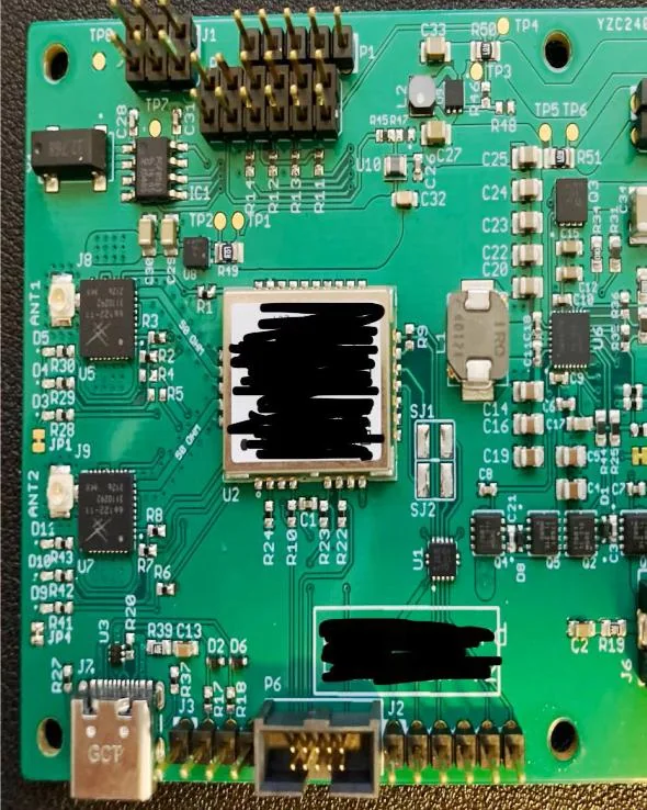
A mission-critical radio powered from a noisy PMIC.

  • The original design used LC filters and capacitors from 1 pF to 4.7 µF around each FEM. They produced high-Q resonance peaks.
  • One Harmony and two 47 µF capacitors now feed VCC_1, VCC_2 and VSUP1 on both modules.
  • Both FEMs operate at the noise floor, with no filters around the chips.

Setup. Two Skyworks RF FEMs on a customer board. Reproduced with customer permission.

Source: Noise Free Innovations 26V2, p. 15

IoT and research

NYU WIRELESS: a faster, more reliable BLE link

12.5 dBless supply noise at the receiver

Published at IEEE WiSNeT 2025 by researchers at NYU Tandon’s RAISE Lab.

  • The LDO output ripple fell from 59 mV to 14 mV, a 12.5 dB reduction.
  • The receiver chain gained at least 10 dB of SNR, and the bitrate doubled at 50 m.
  • The point where SNR collapses moved more than 30 m further out.

Setup. An nRF24L01 2.4 GHz link on Arduino boards, with a Harmony filter in series with the LDO and receiver VDD for A/B testing.

Source: D. Wong, A. Padmanathan and H. Rahmani, “Performance Optimization of Resource-Constrained Wireless Receiver Front-Ends with Power-Centric Design Approaches,” IEEE WiSNeT 2025, pp. 46–49

12.5 dB

less supply noise at the receiver

GNSS

Navigation that stays on the trail

10×better positioning accuracy

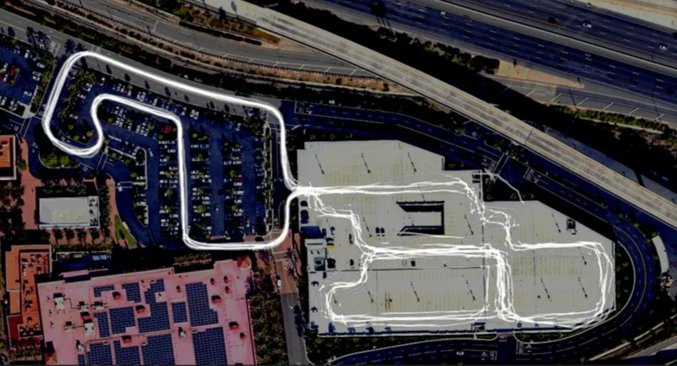
TransSiP PI inside GNSS sports watches, bike computers and a dual-band module.

  • Two watches with the same GNSS chipset ran a 5 km forest trail. One recorded 5.27 km without TransSiP PI, and the other recorded 5.03 km with it.
  • On a route repeated 10 times, including a two-story covered garage, the PI-equipped bike computer’s tracks overlapped consistently.
  • In a drive test, off-road excursions at bends, curve overshoot and erroneous trajectories all dropped with Harmony.

Setup. GNSS products using TransSiP PI. They include a 16 × 12 mm dual-band L1/L5 module built on Sony’s CXD5610, which runs rails as low as 0.65 V and 0.50 V.

Source: Noise Free Innovations 26V2, pp. 16 to 19

Frontier research

Supply-noise elimination at 4 K for quantum computing

DC–20 GHzat 4 K (about −269 °C)

Collaborative research with industry experts on cryogenic power delivery.

  • The goal is power-supply noise elimination from DC to 20 GHz at cryogenic temperature.
  • This builds on the dual Type-B configuration, which has been measured to 20 GHz at room temperature.

Setup. Research collaboration. Details are shared under agreement.

Source: Noise Free Innovations 26V2, p. 10

DC–20 GHz

at 4 K (about −269 °C)

Biomedical wearables

A body-heat-powered health tracker in Japan

4TransSiP PI products inside

MEDIROM’s MOTHER smart bracelet uses TransSiP PI noise-reduction technology. It runs on body heat and needs no charging.

  • Optical heart-rate accuracy with a single LED and detector, at minimal power.
  • In cycling, limits of agreement against a chest strap were +11 / −12 bpm. Published multi-LED designs measure +13 / −27 bpm.

Setup. Single-LED optical heart-rate monitor with Harmony on the LED driver and the AFE, detector and current-ADC rails.

Source: Noise Free Innovations 26V2, pp. 20 to 22. Multi-LED reference: BMC Sports Science, Medicine and Rehabilitation 10:10 (2018).

4

TransSiP PI products inside

Try it on your rail.

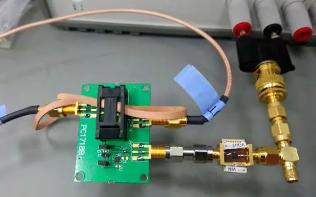
The Type-B evaluation board connects between your supply and your load with two SMA cables.