
How target impedance works, and where it stops
The classic way to design a power distribution network is to pick a target impedance, then add capacitors until the measured impedance profile stays under it. Each capacitor value covers a slice of the spectrum, and each iteration adds parts.
In the example we worked through, the target impedance rises with frequency, from about 65 mΩ to 170 mΩ. Small capacitors can’t lower the overall impedance much. They mostly flatten resonant peaks, and they hold too little energy to support fast transients. Their useful band is narrow, from a few megahertz to about 100 MHz, and only under the lab conditions used to define the profile.
Even when the profile is met, the rail is not quiet. A 50 mA transient at 100 MHz across 171 mΩ is 8.5 mV of noise:
V = I × Z = 50 mA × 171 mΩ ≈ 8.5 mV
The approach has three structural problems:
- It is not portable. Every PDN is tuned to its own layout and load.
- It costs parts. BOM, board area and solder joints grow with each iteration, and every extra joint lowers reliability.
- It is measured in the wrong system. VNAs and TDRs are 50 Ω instruments, but a PDN is not a 50 Ω system. Noise suppression on the real board often differs a lot from what the lab profile predicts.
“This classic approach reflects what the industry has come to accept, rather than striving for true innovation. I often point out that 1 Gbps was the benchmark for 4G and 10 Gbps for 5G, set under ideal lab conditions. Yet in real-world deployments, we settle for much lower data rates. This isn’t due to limitations in silicon technology, but rather the constraints imposed by capacitors and traditional EMI filters, specifically their inability to effectively suppress noise in power distribution networks.” Chih (Desmond) Wong, CEO, TransSiP
Eric Bogatin, Larry Smith and Steve Sandler make a related case in “The Myth of Three Capacitor Values”: decades-old decoupling rules no longer hold for today’s high-speed designs.
The test: one noisy rail, two filters
The noise source. A Picotest VRTS3 board uses a TI LMR10515 buck to convert USB 5 V to 3.3 V. With its 125 MHz and 10 MHz clocks on, it injects strong switching noise into the PDN. That gives a high-power random noise profile from 9 kHz to 3.2 GHz.
Filter A. The 6 GHz broadband noise filter on TI’s LP877451Q1EVM evaluation module uses 15 passives, including a feedthrough capacitor and an inductor.
Filter B. Harmony Type-B uses 3 parts: one Harmony and two 47 µF capacitors.
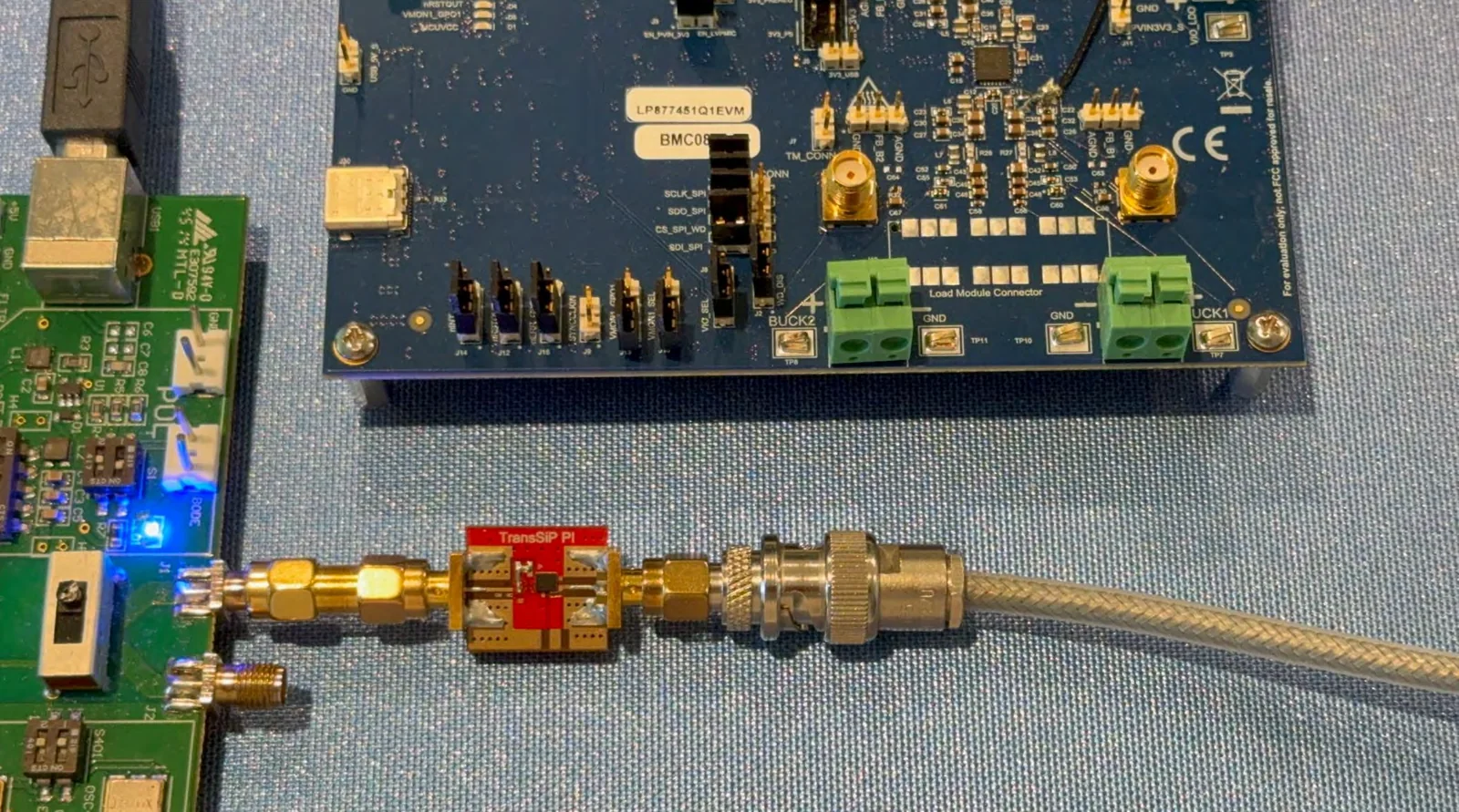
The results
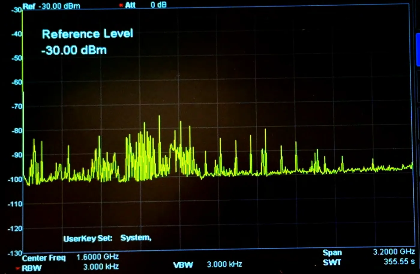
With TI’s filter, the rail was still noisy: just quiet enough to pass EMI compliance, with spurs across the band.
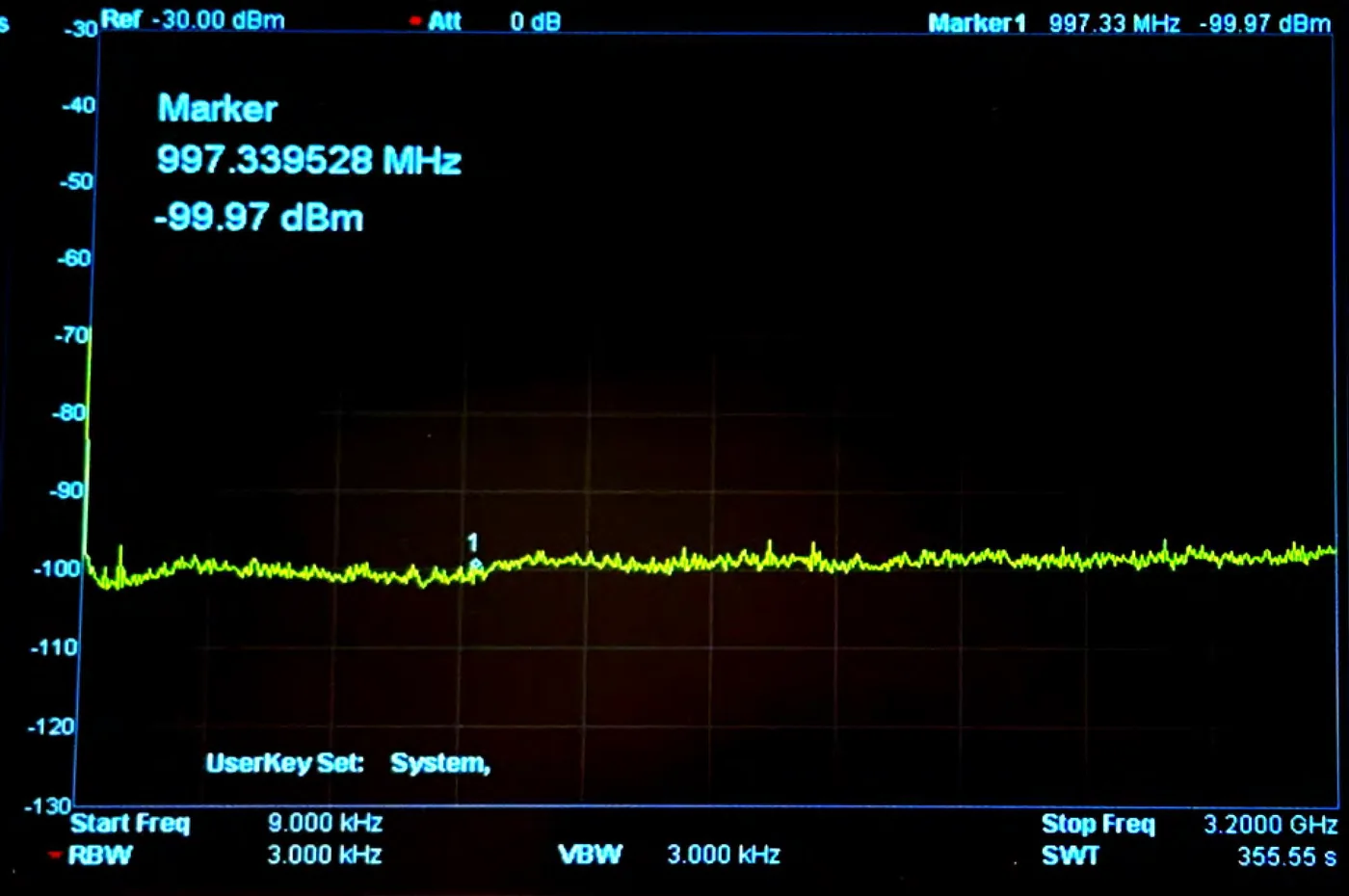
With Harmony Type-B, the trace sat on the analyzer’s own noise floor, −99.97 dBm at 997 MHz. The DC power was delivered at the system noise floor.
| TI 6 GHz filter network | Harmony Type-B | |
|---|---|---|
| Parts | 15 | 3 |
| PCB area | 112 mm² | 7.7 mm² (93% less) |
| Result on the VRTS3 rail | Still noisy, just enough to pass EMI | At the analyzer noise floor |
Why the difference
- Real PDNs are not 50 Ω. A filter network designed and verified as a 50 Ω structure behaves differently when the source and load are a buck converter and a digital load.
- Harmony is designed to work independently of source and load impedance. In Type-B, the bulk capacitors set an anti-resonance near 1 MHz, and Harmony neutralizes their inductance from there upward. The suppression doesn’t depend on tuning to a particular load.
TransSiP sums up the result this way:
- Sustainability: up to 80% fewer passive components, and less electronic waste.
- Compactness: up to 90% less PCB area and fewer layers.
- Universal design: one Harmony and one bulk-capacitor part number for every application.
- PDN stability: micro-ohm ESR, with no phase change and no resonance on the board.
- Efficiency: DC-DC converters become usable for noise-sensitive loads.