
Why a great LDO still leaves noise
Ultra-low-noise LDOs such as TI’s TPS7A94 and ADI’s LT3045 and ADM7150 are the default answer for clean rails. They have three limits that no datasheet hides.
- 1/f noise. Every regulator’s reference and error amplifier has a low-frequency region where the noise rises, and the LDO cannot clean a rail below its own floor.
- PSRR rolls off. Rejection is high at low frequency and falls as frequency rises. Above a few hundred kilohertz, the output capacitor and its parasitics do most of the work.
- There is input PSRR, but no output PSRR. PSRR only describes noise arriving at the LDO’s input. In a real system, long rails, shared grounds and digital loads also put high-frequency noise on the LDO’s output, and nothing rejects it there.
The third limit matters most. When high-frequency noise enters an LDO’s output, the LDO becomes a non-linear mixer, spreading that noise from the 1/f region up to high frequencies. That is why the 1/f noise rises, by as much as 20 dB, and why ground bounce and high-frequency spurs appear on a rail that measured clean on the evaluation board.
Across many customer designs, we see the same thing: the system-level noise floor of switchers and LDOs falls short of the regulator’s intrinsic floor. Harmony wins that headroom back, often another 10 to 20 dB of spectral noise density, including in the 1/f region below 1 MHz.
Newest: two LT3046s made battery-like, from Nokia Bell Labs
Nokia Bell Labs’ Integrated Circuits & Microsystems Research Lab shared this result. A noisy switcher at 6 V feeds an ADI LT3046 at 5 V, and a second LT3046 brings the rail down to 3.3 V. That is two of ADI’s ultra-low-noise, ultra-high-PSRR regulators in series, the textbook way to clean a rail.
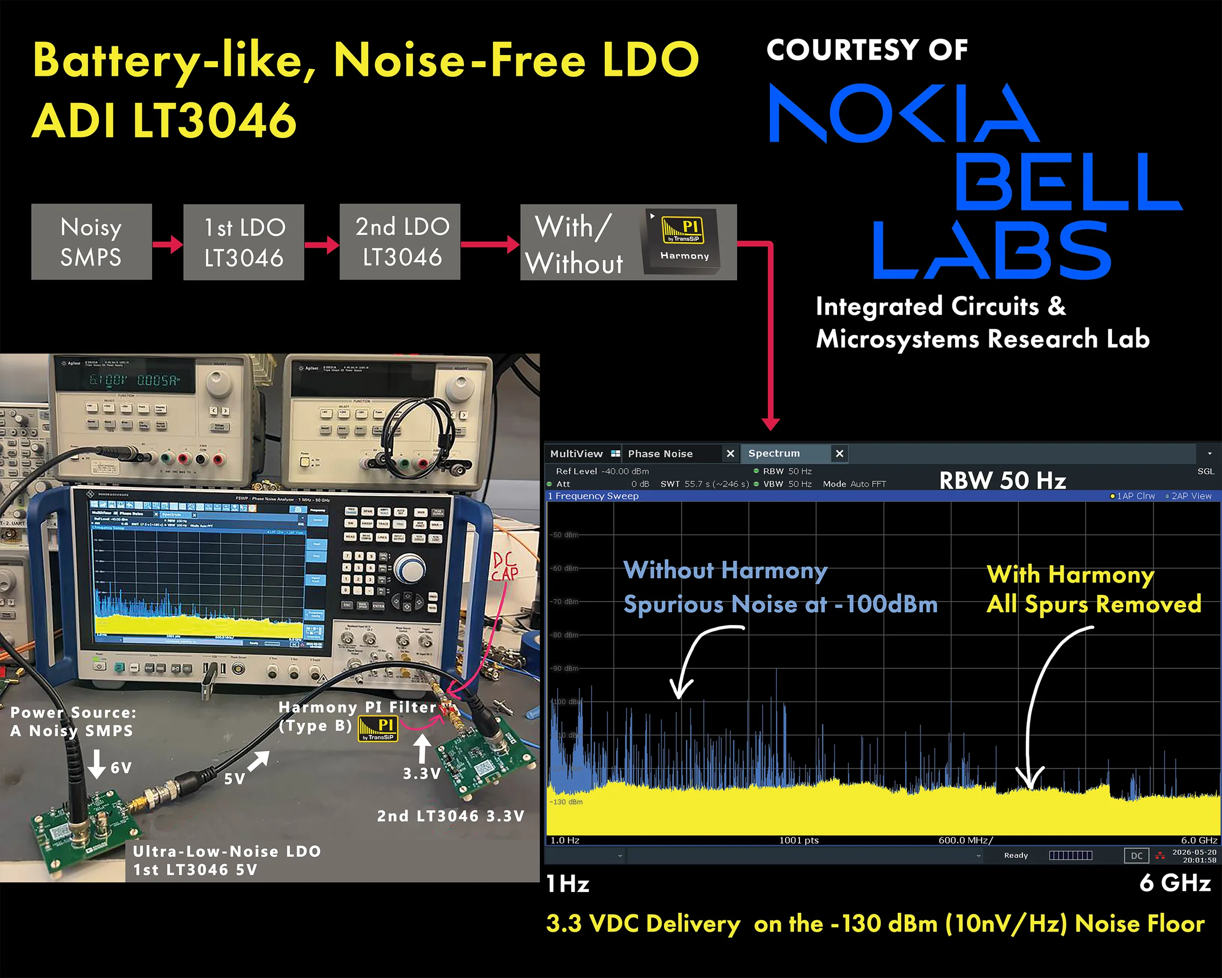
- Two LT3046s, no Harmony: spurious noise still reached about −100 dBm between 1 Hz and 6 GHz.
- With Harmony Type-B after the second LT3046: every spur was removed. The 3.3 V rail sits on the −130 dBm (10 nV/√Hz) noise floor across the whole sweep, measured at 50 Hz resolution bandwidth.
The rail behaves like a battery: DC with nothing riding on it.
TPS7A94: to the analyzer floor, with Nokia Bell Labs
With Nokia Bell Labs, we fed TI’s TPS7A94, its lowest-noise LDO, from a noisy 3.9 V switcher and converted it to 3.3 V. The output was swept from 3 Hz to 6 GHz on a Keysight PXA signal analyzer.
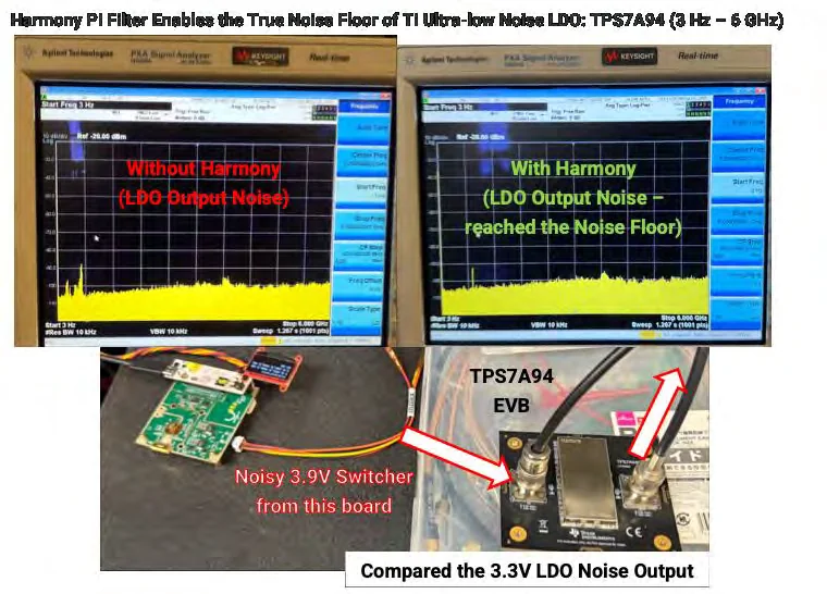
- TPS7A94 alone: noise above 100 kHz was not effectively suppressed, despite the complex filters under the evaluation board’s metal lid.
- With Harmony Type-B at the 3.3 V output: the noise reached the noise floor of the analyzer.
- Harmony Type-B on the noisy 3.9 V switcher, with no LDO at all: the result was the same.
That last result changes the design question. For many rails, “DC-DC plus Harmony” gets you the noise floor without the LDO’s dropout loss. For others, “LDO plus Harmony” or a hybrid makes sense. Either way, the decision now rests on efficiency and headroom rather than on noise.
ADM7150: an active LDO measuring like a switched-off one
A defense entity measured an ADM7150’s baseband noise inside its radio under real operating conditions, and it allowed TransSiP to reproduce the result. With Harmony and a bulk capacitor at the LDO’s output:
| Band | Change with Harmony |
|---|---|
| 1 Hz to 100 Hz (1/f region) | 20 dB lower |
| 1 kHz to 100 kHz | 10 dB lower |
| 200 kHz to 100 MHz | 20 dB lower, with no high-frequency ground bounce |
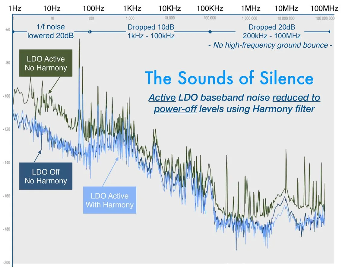
The active LDO with Harmony overlays the measurement of the same LDO switched off. The 20 dB drop in the 1/f region and the missing ground bounce are what you would expect once high-frequency noise can no longer reach the LDO’s output, so there is nothing left for it to mix.
LT3045: three places to put Harmony
Our application note for ADI’s LT3045 puts Harmony Type-B in three positions:
- At VIN, with two 47 µF capacitors, so upstream switching noise never reaches the regulator.
- At the SET pin, replacing the conventional CSET. Harmony’s VIN pin is left unconnected and its VOUT side joins the SET node with bulk capacitors. This gives typically less than 100 µΩ of shunt impedance from 1 MHz to 1 GHz across the set resistor. If start-up time matters, use smaller bulk capacitors here.
- At VOUT, with two 47 µF capacitors, so the load sees the noise floor.
For multi-GHz performance, we lay the board out as though it runs at 6 GHz:
- Stitch the ground layers with many vias around Harmony’s GND terminals.
- Do not return the bulk capacitors’ ground terminals to Harmony’s GND terminal. That couples high-frequency noise from about 1.6 GHz upward. Ground them straight to the plane.
- Extending the VOUT rail by about 5 to 8 mm between Harmony and the capacitors adds about 5 to 10 dB of suppression from 3 GHz to 6 GHz.
What to try on your board
- Put the Type-B evaluation board between your regulator and its load with two SMA cables, and compare the spectrum from a few hertz to the bandwidth of your most sensitive circuit.
- Try the same measurement with the switcher feeding Harmony directly. You may not need the LDO.
- If you keep the LDO, start with Harmony at VOUT, then add VIN and the reference pin if the 1/f region still matters.
Sources
- Nokia Bell Labs, Integrated Circuits & Microsystems Research Lab: battery-like, noise-free LDO, ADI LT3046 with Harmony
- TransSiP, Harmony Quick Start Guide 25V3, §5 and §6 (Harmony Materials Package)
- TransSiP, Optimizing the ADI LT3045 with a Harmony PI Filter, 25V1 (Harmony Materials Package)
- TransSiP, Noise Free Innovations 26V2, p. 13: ADM7150 baseband noise in a defense radio, reproduced by permission
- Texas Instruments, TPS7A94 product page
- Analog Devices, LT3046 product page
- Analog Devices, LT3045 product page
- Analog Devices, ADM7150 product page