
Power integrity is now a speed limit for storage
A 2024 paper from Samsung’s memory business at IEEE EPEPS estimates that power-supply-induced jitter (PSIJ) from system noise can take more than 42% of the eye-width budget of a PCIe Gen 6.0 SSD. Four trends make it worse with each generation:
- 32 GT/s PCIe Gen5 signaling, and faster in Gen6, sets tighter PDN impedance targets than ever.
- Merged IO rails for the controller and the NAND create multi-channel noise coupling.
- 8 or 16 ONFI channels switching at once add up to simultaneous switching noise (SSN).
- EDSFF and M.2 form factors leave very little room for decoupling capacitors.
Merged IO rails create a perfect noise storm
To save cost and keep the power plane whole, many SSDs merge the controller’s IO supply with the NAND IO supply. Every ONFI channel then switches current into the same PDN cavity:
- Each channel generates switching noise at its own characteristic frequencies.
- When channels line up in phase, their noise currents add constructively.
- If that excitation lands on a PDN resonance peak, the rail can collapse.
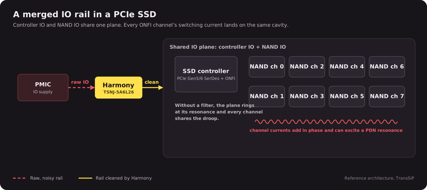
When the system hits a resonance at the right frequency, multi-channel noise currents can build into PDN “rogue waves” that a discrete capacitor network can’t damp.
Why discrete parts fall short
| Limitation | Impact on SSD design |
|---|---|
| High-Q resonance peaks | MLCCs and ferrite beads can’t fully damp them |
| Board area | 6 to 10 capacitors plus a bead take 18 to 25 mm² per rail |
| Limited bandwidth | Each part works only in a narrow frequency range |
| Saturation | Ferrite beads lose impedance under DC bias |
| Thermal hotspots | Many components concentrate heat |
No conventional discrete network holds a flat, ultra-low impedance across the full 1 MHz to 1 GHz range that PCIe Gen5/6 SSDs need.
A different kind of power-integrity part
Harmony is a single passive PI filter that removes switching-noise jitter in both the frequency and time domains, so the load sees a clean, stable DC supply.
| Parameter | Harmony TSNJ-5A6L26 |
|---|---|
| Size | 2.2 × 2.6 mm (about 5.7 mm²) |
| Rating | 5 A at up to ±6 V |
| Noise shunting | 1,000 times better than prior art |
| SNR improvement | +10 dB in sensing and RF systems |
Impact 1: a lower bit error rate
Harmony removes the multi-channel resonance on a merged IO rail. That suppresses SSN on the NAND interface and PSIJ on the PCIe SerDes, and cleaner power means a wider eye at 32 GT/s.
| Metric | Without a filter | With Harmony | Change |
|---|---|---|---|
| SNR | Baseline | +10 dB | 3.16 times lower noise floor |
| Noise shunting | Baseline | 1,000 times better | Three orders of magnitude |
| Bit error rate (projected) | About 10⁻¹² | About 10⁻¹⁵ | 1,000 times fewer errors |
Impact 2: higher energy efficiency
Harmony holds impedance in the micro-ohm range across a very wide bandwidth, which cuts losses in the PDN during fast current transients. In our PDN impedance measurement, it took 1.129 Ω at 127.8 MHz down to 153 µΩ, a reduction of more than 1,000 times.
| Parameter | Projected improvement |
|---|---|
| PDN impedance | More than 1,000 times lower at critical frequencies |
| Voltage margin | Under 1% droop, compared with 3 to 5% |
| Performance per watt | Rises directly with lower losses |
Impact 3: a more stable system
| Risk | Discrete network | Harmony |
|---|---|---|
| Resonance peaks | Present, hard to damp | Removed |
| Worst-case excitation | Can collapse the rail | Filtered before it reaches the load |
| Multi-channel coupling | Uncontrolled | Suppressed |
Smaller, simpler boards
| Solution | Area per rail | Four-rail SSD |
|---|---|---|
| Discrete: 6 to 10 capacitors plus a bead | 18 to 25 mm² | 72 to 100 mm² |
| Harmony PI Filter | 5.7 mm² | 22.8 mm² |
| Saved | 12 to 20 mm² | 49 to 77 mm² |
- A simpler BOM: one part number for every rail, with Harmony and two bulk capacitors replacing tens of passives.
- Faster time to market: no rail-by-rail PDN co-simulation, and the same design carries across models.
- Lower power: fewer retries from bit errors, and no need to budget voltage margin for noise above 10 mV.
DDR5 and DDR6: the memory wall
Memory bandwidth has to keep up with CPUs and GPUs. Mainstream JEDEC-speed DDR5 modules run at about 6,400 MT/s at 1.1 V. Faster kits get there by overclocking and raising the supply toward 1.4 V, which costs power and heat.
| Frequency range | Typical target PDN impedance | What sets it |
|---|---|---|
| DC to 2 MHz | VDD ≤ 30 mΩ, VDDQ ≤ 40 mΩ | VRM response and bulk capacitance |
| 2 to 100 MHz | Falling to under 10 mΩ | Mid-frequency decoupling (MLCCs) |
| 100 MHz to 1 GHz | Under 5 mΩ, design dependent | On-package and on-die capacitance |
The JEDEC ripple limit for DDR5, 2% or about 22 mV, reads like a single number. In practice it depends on frequency and on where you measure, and the margins keep shrinking:
| Standard | VDD and VDDQ | Ripple |
|---|---|---|
| DDR5 | 1.1 V ± 5% | 2% or less |
| DDR6 (expected) | About 0.9 V | 1.5% or less |
Getting there means dealing with package balls versus die pads, low-frequency droop versus mid-band antiresonance, and burst-mode transients, which usually takes wide-bandwidth co-simulation.
A paper simulation: DDR5 with near-ideal power
TransSiP modeled a DDR5 channel with near-ideal power integrity: 10 to 50 µVpp of residual broadband noise at the die, no mid-band antiresonance between 20 and 200 MHz, and no burst-correlated droop. The baseline was 50 mVpp of ripple at the die.
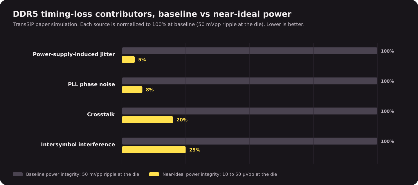
In the simulation:
- PSIJ fell from 120 to 150 fs RMS to under 10 fs RMS.
- Effective eye width recovered by 8 to 15%, depending on the pattern.
- Marginal channels gained one to two speed bins.
- High-speed operation at 1.1 V instead of 1.4 V would save about 20% of the power.
The takeaway: with near-ideal power, 8,400 MT/s and faster can run reliably at 1.1 V, and cooler. These are simulation results, not measurements.
To try Harmony on your own SSD or memory rail, start with the Harmony evaluation board, or talk to TransSiP applications engineering.
Sources
- TransSiP, Harmony for Memory (available on request)
- Y. Ko et al., "PCIe Gen 6.0 SSD PSIJ Estimation Based on Early Design Stage Jitter Sensitivity Measurements," 2024 IEEE 33rd EPEPS
- TransSiP case study: PDN impedance before and after Harmony, 100 kHz to 3 GHz
- TransSiP, Harmony PI Filter datasheet TSNJ-DS-R009, Rev 9