
Every link in an AI cluster starts on a power rail
AI clusters move data over copper inside the rack and over fiber between racks, and the newest pluggables run at 2.4T and 3.2T. Whether the link is an active copper cable or an optical transceiver, the same few blocks keep appearing: a SerDes, a DSP or retimer, transimpedance amplifiers (TIAs), photodiodes, linear drivers, ADCs and a reference clock. Each one turns supply noise into jitter or amplitude noise, and the bit error rate pays for it.
All seven form factors below also share one dependency on the host motherboard: the host SerDes and its 625 MHz reference clock. So Harmony has two jobs in every architecture. It cleans the rails inside the module, and it cleans the host rail and clock that the whole link depends on.
Why 2.4T and 3.2T make Harmony necessary
A 2.4T pluggable carries eight lanes at 300G each, and a 3.2T pluggable carries eight lanes at 400G. Every step up in lane rate shortens the time each symbol spends on the wire, but the noise on the board’s power rails stays the same. So the same power-supply-induced jitter takes a bigger and bigger share of the eye.
| Module | Lane rate | Time per symbol | Share of the symbol taken by 100 fs of jitter |
|---|---|---|---|
| 800G | 8 × 100G | about 18.8 ps | about 0.5% |
| 1.6T | 8 × 200G | about 9.4 ps | about 1.1% |
| 2.4T | 8 × 300G | about 6.3 ps | about 1.6% |
| 3.2T | 8 × 400G | about 4.7 ps | about 2.1% |
Symbol times assume PAM4 with the same coding overhead as today’s 100G and 200G lanes. 400G lanes may use other modulation, but the trend is the same.
At 800G and 1.6T, a careful decoupling network can usually keep supply-induced jitter inside the budget. At 2.4T and 3.2T it runs out of room. The rail has to sit at its intrinsic noise floor, with no spurs left for the SerDes, TIAs and drivers to turn into jitter. That is the job Harmony does: its noise elimination isn’t capped at a dB figure, it takes the rail down to the source’s own floor, and its attenuation holds for any source and load impedance.
What’s inside each module
| Form factor | DSP | TIA | Photodiode | Linear driver | ADC | Voltage ref | DC-DC | Onboard SerDes |
|---|---|---|---|---|---|---|---|---|
| ACC active copper cable | No | No | No | ● | No | No | No | No |
| AEC active electrical cable | ● | No | No | No | ● | No | ● | ● |
| AOC active optical cable | ● | ● | ● | ● | ● | No | ● | ● |
| OSFP transceiver | ● | ● | ● | ● | ● | No | ● | ● |
| ELSFP external laser | No | No | No | No | ● | ● | ● | No |
| LPO linear pluggable optics | No | ● | ● | ● | No | No | ● | No |
| NPO near-packaged optics | No | ● | ● | ● | No | No | ● | No |
Every row also relies on the host SerDes and the 625 MHz clock on the motherboard.
Where Harmony goes, form factor by form factor
- ACC: in-line host shielding. A Harmony at the connector scrubs the raw 3.3 V host rail before it reaches the unretimed copper driver. Another protects the host clock and SerDes path.
- AEC: onboard and host protection. Harmony cleans the module’s local DC-DC rails, so power-supply noise doesn’t turn into jitter in the onboard SerDes.
- AOC: protects both halves of the module. The digital SerDes and the analog optics share one internal power plane. Filtering each load isolates the fragile optics from the digital switching.
- OSFP: defends against high-current ripple. The module’s core DC-DC regulators carry heavy current. Harmony keeps their sub-millivolt switching spikes out of the TIAs and the onboard SerDes.
- ELSFP: shields the analog telemetry loops. Harmony keeps the precision voltage reference and current source quiet, so local DC-DC noise can’t raise the laser’s relative intensity noise (RIN).
- LPO: one Harmony per TIA bank. With no DSP to clean up the signal, the module depends entirely on the host SerDes and clock, so its power has to be flawless. Separate filters isolate each multi-channel TIA bank.
- NPO: a noise barrier on the substrate. Next to a GPU, the optical TIAs share a substrate with the GPU’s high-power switching. Harmony isolates them from those spikes.
Four reference architectures
Each diagram is drawn for 2.4T and 3.2T modules, with eight lanes at 300G or 400G. Dashed red is a raw, noisy rail, yellow is a rail Harmony has cleaned, and grey is high-speed data or clock. Click any diagram to enlarge it.
Active copper cable (ACC)
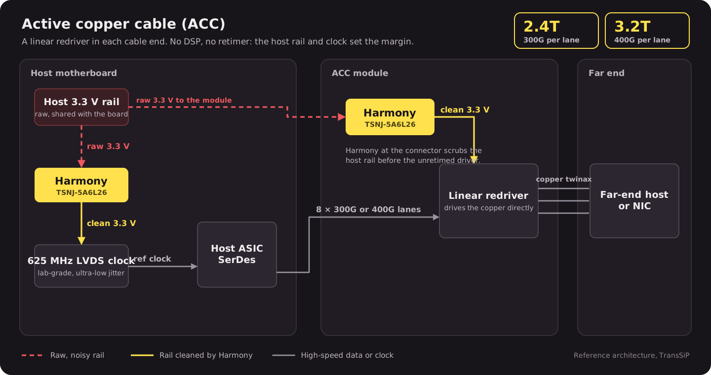
An ACC has no retimer, so whatever noise reaches the redriver goes straight onto the copper. The cleanest place to stop it is where the host rail enters the cable.
Active electrical cable (AEC)
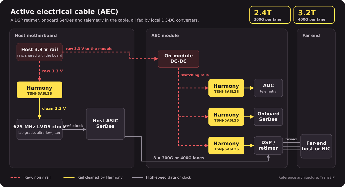
The DSP retimer can clean up a degraded signal, but only if its own SerDes isn’t being modulated by the DC-DC converter a few millimeters away.
Linear pluggable optics (LPO)
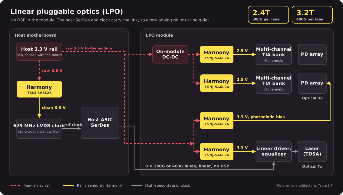
LPO removes the DSP to save power and latency. The trade-off is that the host SerDes now sees every bit of noise the analog front end adds, so each TIA bank gets its own filter.
Near-packaged optics (NPO)
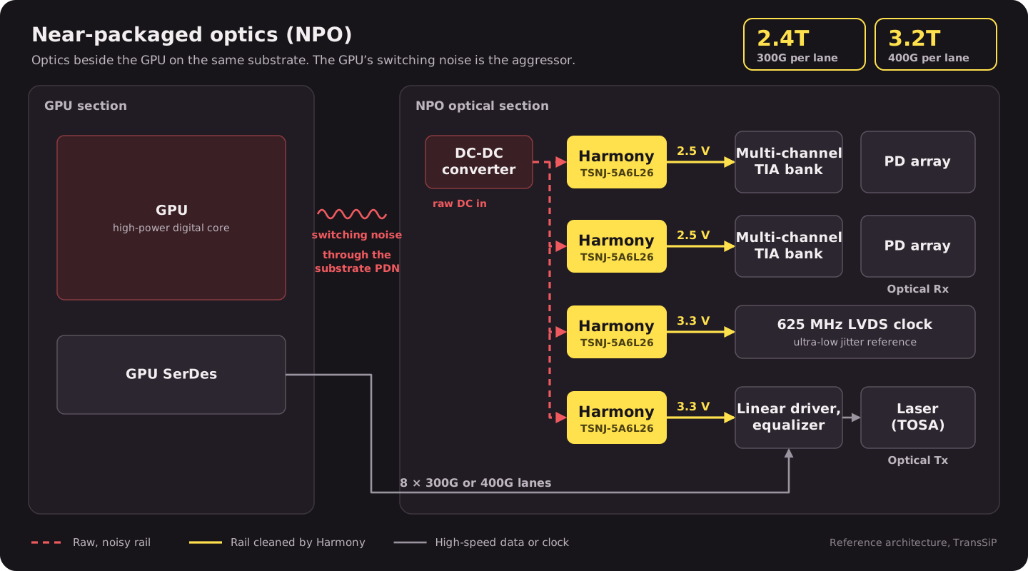
Moving the optics next to the GPU shortens the electrical path, but it puts the most sensitive analog circuits beside the noisiest digital load in the system.
The clock is part of the power problem
Every architecture above ends at a 625 MHz LVDS reference clock on the host board, and that clock’s jitter lands in every link it times. We measured a 625 MHz LVDS oscillator at 15.73 fs RMS jitter (12 kHz to 20 MHz) running from its own supply with Harmony. Every spur from about 10 kHz to 20 MHz was removed, leaving a −161 dBc/Hz floor.
One part for every slot
The same TSNJ-5A6L26 fits each position in these diagrams:
- Small enough for a pluggable module: a 2.2 × 2.6 mm LGA, rated 5 A at up to ±6 V.
- Broadband: suppression from DC to 6 GHz, and up to 20 GHz with two in series.
- Predictable: its attenuation holds for any source and load impedance, so it behaves the same on a host rail, a DC-DC output or a substrate.
- Already in service: Harmony is designed into optical modules, rack interconnect and AI servers today.
To evaluate it on your own rail, start with the Harmony evaluation board, or ask TransSiP for the full reference architectures.